Greta Friedrich · 14 September 2026
Tracing Curved Edge Dynamics in Parametric Fabrication Workflows for Custom Component Development
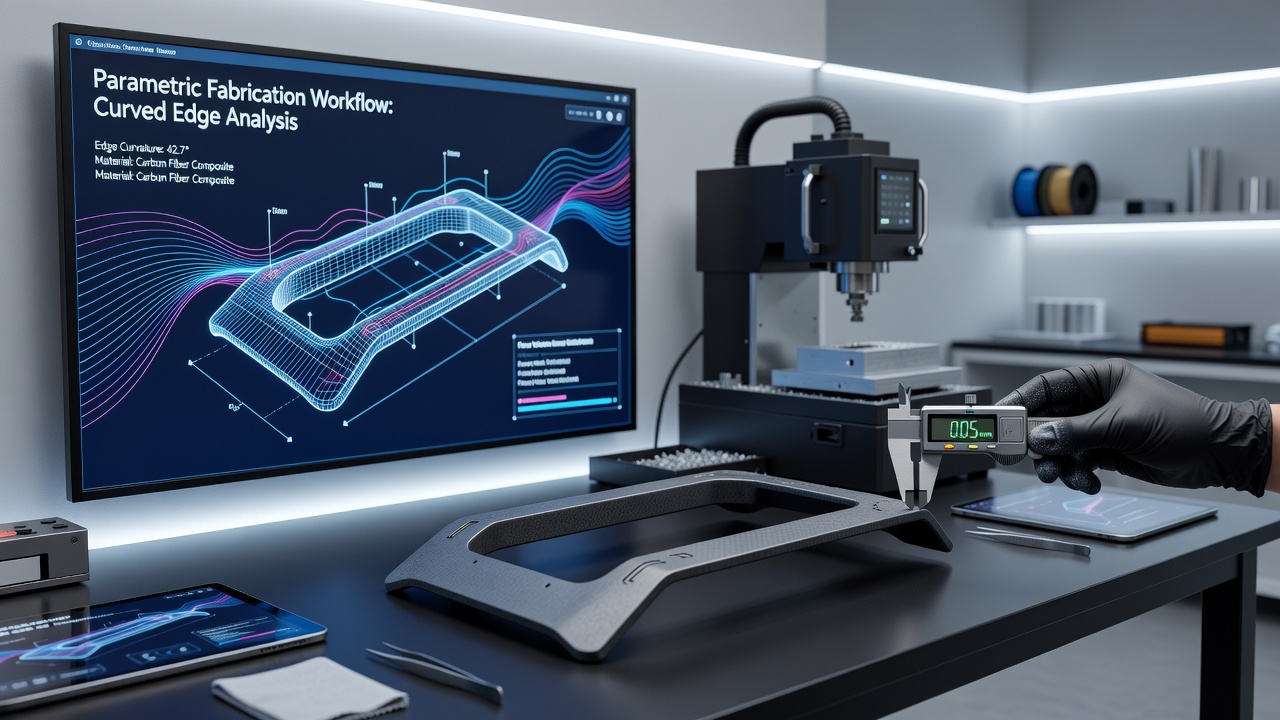
Parametric fabrication workflows enable designers and engineers to generate custom components through rule-based modeling systems that respond to input variables in real time, and tracing curved edge dynamics forms a core element within these processes because it governs how smooth transitions and organic shapes translate from digital models into physical parts. Researchers in digital manufacturing observe that curved edges introduce variables such as curvature continuity, tangent alignment, and offset calculations that differ markedly from straight-line geometry, which means algorithms must account for local radius changes and surface normals at each point along the path.
Core Principles of Curved Edge Tracing
Curved edge tracing begins with the extraction of boundary curves from parametric surfaces, after which specialized functions evaluate derivative information to maintain G2 continuity across adjacent patches, and this step proves essential when components undergo CNC milling or robotic deposition where toolpaths follow the exact contour. Data from fabrication studies indicate that discontinuities in curvature often lead to visible faceting or stress concentrations once parts are produced, so software platforms incorporate NURBS evaluation routines that sample points at adaptive densities based on curvature magnitude. Those who work with these systems note that parameter spacing adjusts automatically in high-curvature zones while remaining coarser on flatter sections, which reduces computational load without sacrificing accuracy.
Integration Within Parametric Workflows
Integration of edge tracing into full parametric pipelines occurs through scripting environments where users define relationships between input parameters and output geometry, and changes to a single variable propagate through the model to update all affected curves instantly. Fabrication teams at automotive prototyping facilities rely on this linkage because it allows rapid iteration on parts such as aerodynamic fairings or ergonomic handles that feature compound curves. Observers note that the workflow typically sequences through surface generation, curve extraction, offset creation for tool compensation, and finally G-code or robot path output, with each stage preserving the dynamic properties of the original edges.
Technical Challenges in Dynamic Tracing
Technical challenges arise when multiple curved edges intersect or when surfaces exhibit varying degrees of torsion, because standard intersection solvers can produce ambiguous results that require additional constraints to resolve. Research indicates that hybrid approaches combining analytical solutions with numerical refinement deliver more stable outcomes, particularly on freeform surfaces where traditional projection methods fail. In one documented case experts found that implementing curvature-aware sampling reduced path deviation by measurable margins during five-axis machining trials, and the same techniques transferred effectively to additive processes where material deposition must follow precise trajectories. September 2026 brings scheduled updates to several open-source parametric libraries that introduce improved handling for non-uniform rational B-spline edge networks, which should address lingering issues in multi-patch assemblies.
Applications Across Industries
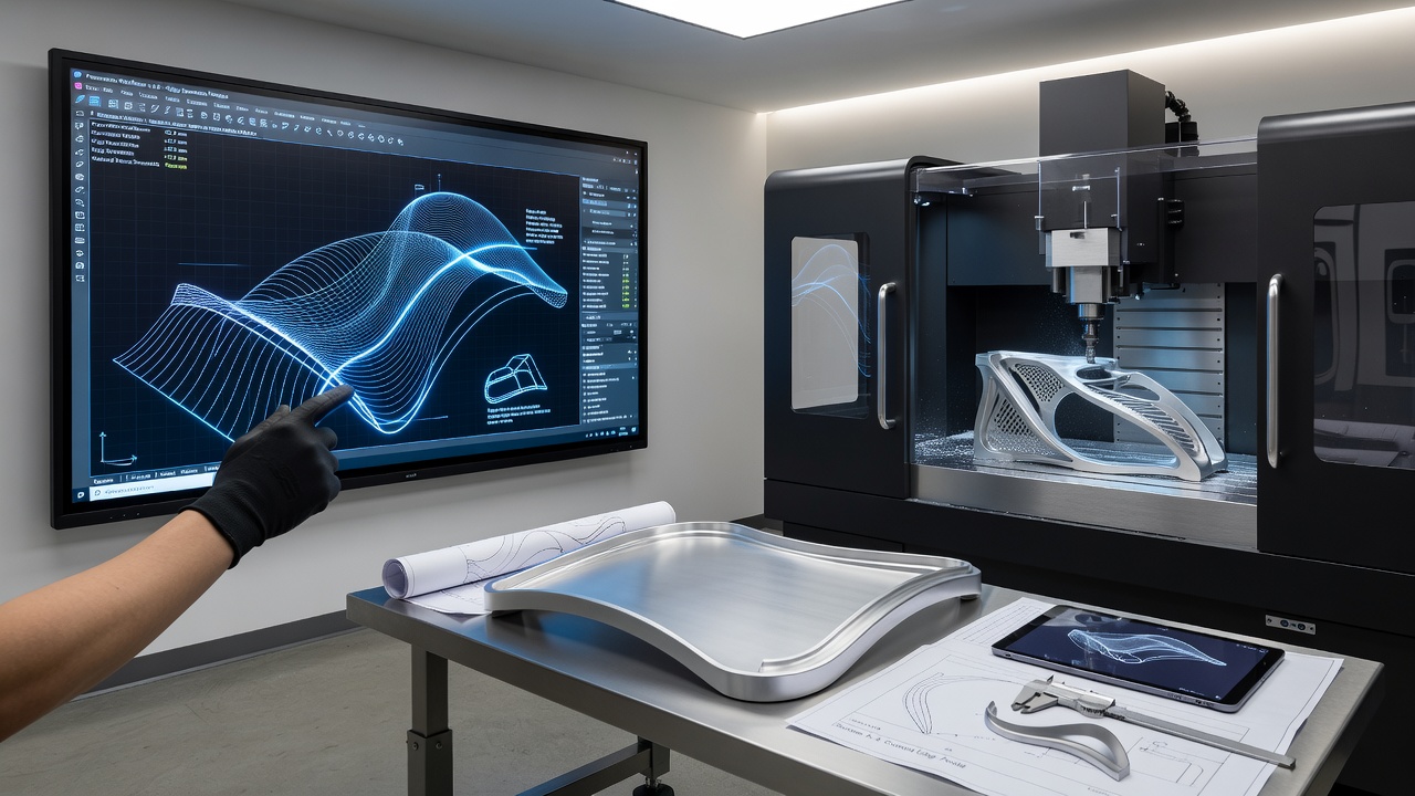
Applications span architecture, aerospace, medical device manufacturing, and consumer product design, where custom components frequently incorporate ergonomic or aerodynamic curves that cannot be approximated by linear segments. According to findings published by the National Institute of Standards and Technology, precise edge tracing correlates directly with improved fit and finish in assembled systems, while reports from the Canadian Institute for Advanced Manufacturing highlight similar benefits in lightweight structural parts produced via directed energy deposition. These studies emphasize that consistent edge behavior across digital and physical domains reduces post-processing requirements and material waste.
Software Tools and Emerging Standards
Software tools supporting these operations include established platforms that combine visual scripting with direct geometry kernels, and emerging standards aim to formalize data exchange formats that carry curvature information alongside traditional mesh or solid representations. Industry organizations continue to develop validation benchmarks that test tracing accuracy under controlled curvature conditions, providing metrics that manufacturers use to certify their workflows. What's interesting is how these benchmarks now incorporate real-time feedback loops that simulate fabrication forces on curved surfaces, revealing interactions that static analysis overlooks.
Conclusion
Tracing curved edge dynamics within parametric fabrication workflows supports the reliable production of custom components that meet exacting geometric and functional requirements, and ongoing refinements in algorithms together with scheduled software advancements position the field for continued precision gains. Organizations that adopt these methods gain measurable advantages in repeatability and material efficiency, while collaborative research efforts across regions continue to expand the range of geometries that can be fabricated with confidence.